
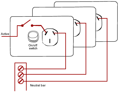
Moving A Power Point
Sep 2016
**WARNING**
ONLY A LICENSED QUALIFIED BRISBANE EMERGENCY ELECTRICIAN MAY MOVE A POWER POINT IN AUSTRALIA. IT IS ILLEGAL TO TRY AND MOVE A POWER POINT YOURSELF. THIS ARTICLE IS FOR INFORMATION & INTEREST ONLY AND IS IN NO WAY INTENDED TO INSTRUCT OR GUIDE THE READER TO PERFORM THIS THEMSELVES. AN ALTERED POWER POINT THAT HARMS A PERSON OR RESULTS IN DAMAGE TO A PROPERTY MAY RESULT IN CRIMINAL NEGLIGENCE. IT WILL VOID HOME AND CONTENTS INSURANCE CONTRACT.
So we perform this quite a bit and its interesting to see how its done, but we must stress that you must not try this yourself, it is extremely dangerous, only a licensed electrician can do this. Ok, so let’s have a look at how they do it.
Step 0: Proper attire
An electrician will wear thick rubber boots and insulated gloves whilst performing any work in order to reduce the risk of electrocution by adding extra impedance protection in the case of error or failure.
Step 1: Disconnect the power at the mains fusebox / switchboard
This is obviously the most important step. Before working with wires, the electrician must ensure that the wire is cut off from the supply and therefore not ‘live’. To do this the electrician identifies which section of the circuit the power point sits in, and then turns this section of the circuit off at the mains fusebox or switchboard. If unsure the master switch can be disabled so that all power is disconnected to all parts of the circuit.
Step 2: Test the power point
Before proceeding further the electrician has to test that the line is in fact dead. So one way to do this is to plug in a device or appliance that they are certain is functioning correctly. They turn it on and confirm that it doesn’t work. They then use another appliance to double check. Double checking and redundancy is the name of the game with safety and electricity. Now that they have confirmed both appliances (which are known to be operational) are dead they then use a high voltage multimeter or electrical test screw driver to test again.
Only once all these tests are passed can the electrician proceed to handle the wires. It is interesting to note that an appropriate appliance should be used to test the disconnection of the power first, because within that circuit segment (in which the power point lies and which has hopefully just been disconnected at the mains switch) multiple power points (and therefore appliances, devices and other plant) are likely to wired to it, which means there may be residual capacitance available in that circuit segment. The appliance should draw this remaining charge, whereas a voltmeter will not.
Step 3: Remove the power point
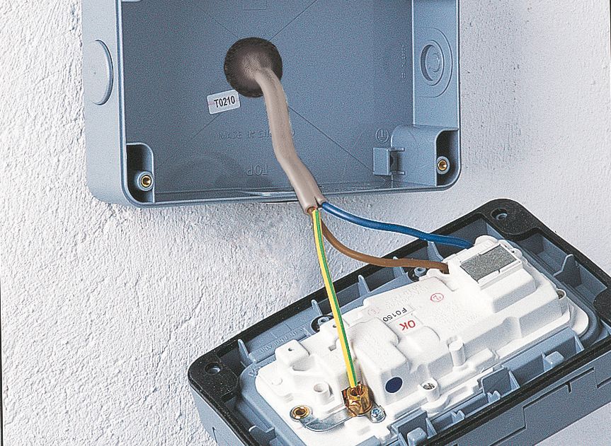
To remove the power point from the wall the electrician first removes the cover/skirt/face plate from the power point by gently pulling on it. Underneath are two screws that mount the power point to the wall. Unscrewing these detaches the power point from its mounting, some power points screw into a metal wall mount plate that sits behind the Gyprock. The electrician first removes a single screw then rotates the plate down exposing the hole behind to determine what kind of mounting has been used, and then gently holds the mounting with pliers as the other screw is removed, so that the mounting plate doesn’t fall down the wall cavity.
Step 4: Remove the wires from the back of the power point
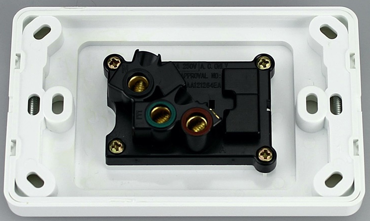
The electrician unscrews the bolts that hold the wires into the power point connection. Once loose these wires are taped and capped up. To stop the wires accidentally falling back into the wall cavity they can be taped to an object (such as a hammer) or to the wall or bench.
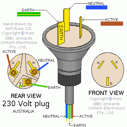
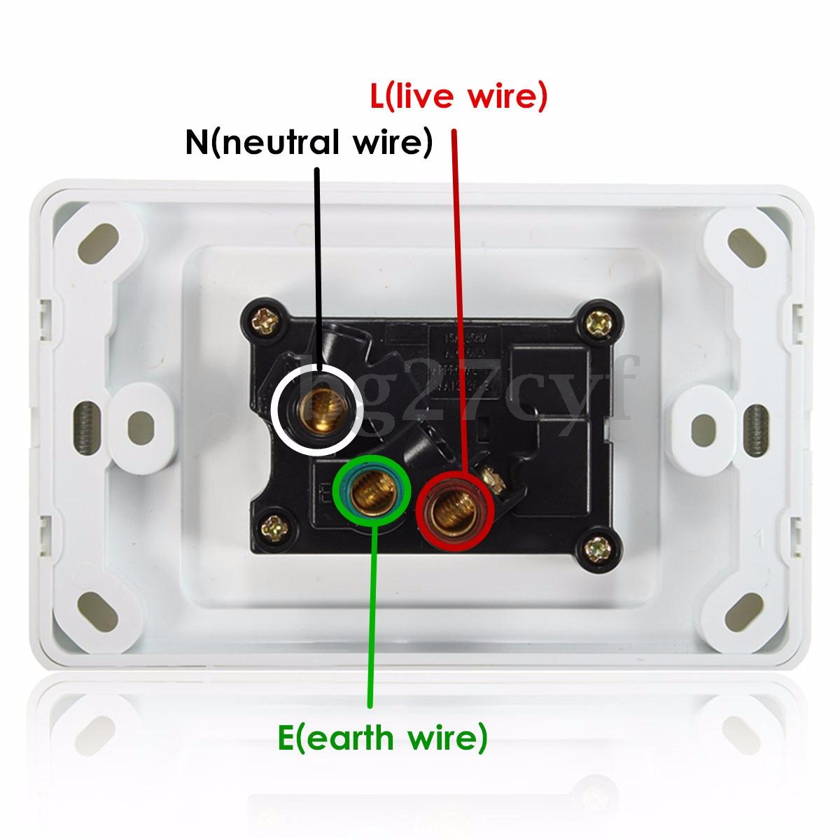
The colour of the wire indicates what it is. Remember that: Brown – is the active phase; Blue – is the neutral, Green + Yellow – is earth ground. If uncertain a photo can be taken of the wiring arrangement on the back of the plate so that the wires are reconnected in the correct spot. The wiring arrangement of a power point is indicated using colour labelled sockets and is pictured here in this figure; the red socket is for the active phase (or live, which is the brown wire), the black socket is for the neutral (blue wire), and the green socket is for the earth ground (green + yellow wire). The wiring arrangement of the plug is shown below.
Step 5: Cut the new hole
Using a pencil sketch an accurate outline of the required hole onto the Gyprock. Drill a hole (atleast 5mm) inside each of the four corners of the rectangle, open the holes up with a file. Now that the hole is of decent width fit a jigsaw, hacksaw, or blade, into a hole and cut between holes along the perimeter. Clean up the edges with a file or sandpaper if a neat edge is required.
The electrician must exercise extreme caution whilst cutting through the wall, if a live wire is accidentally severed or sheared it could result in electrocution and death. For this reason the electrician makes extra effort to check that there are no wires in the cutting path and to cut at wall depth only and no deeper.
Step 6: Extend the wires (optional)
Now that the new hole is cut the electrician can see if the wires will reach then new location. If they do not then the wires will need to be extended. To do this the recommended approach is to use a mains wire extension box, these are commonly used to join/extend wires in Australia. This is pretty straight forward. The electrician uncaps the wires, inserts each into the correct socket then screws up the clasping mechanism. Then the lengths of new wire are cut to size and the insulation is stripped on both ends to about 40mm. These new wires are each inserted into their correct socket and again screwed tight. The box itself is then closed with screws, and can then be placed inside the wall cavity.
It is also possible to extend the wires by joining them using the solder and heatshrink technique, if you are interested to see how an electrician might do this then refer to this blog post on joining wires.
Step 7: Wire up the power point in the new location
Before joining the wires to the back of the power point plate, first the electrician takes the wall mounting back plate and threads the wires through it, then inserts this plate into the hole, and tapes it roughly in position so that it is ready to be screwed in, in the next step.
Now the wires can be joined to the power point plate. Similarly to how they were removed, they are inserted into their appropriate sockets and screwed in. The electrician must take care to screw the wires into the correct socket. They may check the photo they took before, or the previous figure has been reproduced here but with additional labelling for clarity.
Step 8: Mount power point in the new location
The electrician now mounts the power point to the wall using the internal wall mounting that was loosely housed in the previous step. So first the electrician places the power point into the hole and marks the location of both screw holes on the wall by means of a pilot hole, which can be done by applying small pressure on the Gyprock with the screw. The electrician then pulls the power point out of the hole in order to access the mounting plate behind. The power point is rotated so that the correct screw hole is aligned to the mark that was just made but that the large hole in the Gyprock wall can be accessed by hand.
Then the screw is torqued through the Gyprock enough to protrude a small distance out of the other side. The mounting plate can now be aligned using the protruding screw and once aligned this screw is torqued a little more, just enough so that it doesn’t fall out. The other screw is then torqued in through the Gyprock but not through the power point, and the other side of the interior wall mounting is aligned to it. Once both holes are aligned, the mounting plate should be taped in place. The last screw is removed from the wall. The power point is then placed in its correct location and the removed screw is then inserted and tightened. The original screw can then be tightened up. Now that the power point is housed correctly on the wall the cover plate is pushed on.
Step 9: Patch the old hole
Here we are assuming that the electrician is working with a Gyprock wall. Cut a piece of stiff cardboard to cover the shape of the hole with atleast an additional 10mm overlap. Cardboard of 5-8mm thickness should do fine. Poke a hole through the cardboard then feed sum string through it and tie off the string on one side so that it doesn’t pull back through. Work the cardboard into the hole (by folding or other) and pull it into position with the string, ensure there are no gaps.
Apply PVC wood glue to the perimeter/edges where the cardboard meets the Gyprock. Blast the glue with a hair dryer in order to partially set it so that you can let go of the string. Wait for this to dry completely. Add water to plaster powder and mix, apply the wet plaster to the hole with a paint scraper, and distribute until even coverage is achieved. Wait for it to set completely. Sand the plaster back to achieve a smooth finish, if required apply more plaster and repeat step. Using the same (or very similar) colour, paint over the plaster feathering the edges so that when dry it is indistinguishable as a fresh coat.
Step 10: Turn power back on and test
Turn the power back on at the mains switch, and test that the power point is working by running an appropriate appliance through the power point.
OK and that’s all there is to it. Job done. Remember that only a qualified licensed emergency electrician can do this. It is illegal to try and do it yourself and is EXTREMELY DANGEROUS, you risk electrocution and death. So remember to exercise extreme caution around electricity at all times and never do it yourself, always hire a professional.